Why Flow Control Needs a 3-Way Valve
A standard 2-way valve only provides on/off isolation, allowing flow or blocking it. The 3-way valve introduces a critical third dimension: the ability to switch, mix, or divert flow between two different lines. Understanding its internal mechanism is vital for correct process control design.
The most common 3-way valve design is the 3-way Ball Valve, and its function is entirely determined by the shape of the bore drilled through the central ball.
I. Core Mechanism: How a 3-Way Valve Works
The principle of a 3-way valve is straightforward: it uses a 90° rotation of the internal mechanism (usually a ball) to change the path of the fluid. The three ports are typically labeled Port A, Port B, and a Common Port (C or IN).
A. L-Port Flow Pattern (Diverting/Switching)
The L-Port (or L–pattern) is the most common configuration, known primarily for its diverting or switching function.
Internal Structure: The bore through the ball is shaped like the letter ‘L’.
0° Position (Path 1): Flow connects the Common Port (C) to Port A, blocking Port B.
90° Position (Path 2): Flow connects the Common Port (C) to Port B, blocking Port A.
180° Rotation: The L-Port typically does not switch past 90° in its primary design, as further rotation often leads to a blocked state.
Primary Application: Diverting a single incoming stream to one of two destinations (e.g., sending coolant to either Process A or Process B).

B. T-Port Flow Pattern (Mixing/Switching)
The T-Port (or T–pattern) offers much greater flexibility and is primarily used for mixing or more complex switching tasks.
Internal Structure: The bore through the ball is shaped like the letter ‘T’.
0° Position (Mixing): All three ports (A, B, and C) are connected simultaneously. This allows two streams (A and B) to mix and exit through the common port (C).
90° Position (Diverting): Flow connects C to A (blocking B).
180° Rotation: Flow connects B to A (blocking C). This allows for line crossover or straight-through flow by bypassing the common port.
Primary Application: Mixing two fluids (e.g., blending hot and cold water in HVAC systems to achieve a set temperature).

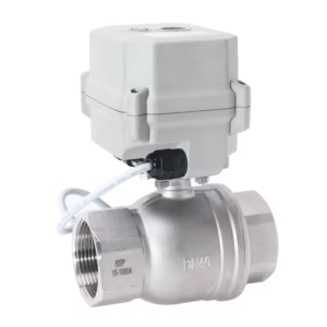
II. Actuation and Control: The Automated 3-Way Valve
The ability to automatically switch or mix fluid streams is what drives the high commercial value of 3-way valves, directly addressing the query: “3-way valve with actuator working“
1. Actuator Types
The actuator is the mechanism that rotates the ball 90° (or 180°):
Manual: Hand lever or gear; requires human intervention.
Pneumatic Actuator: Uses compressed air to drive a piston or vane. These are fast and reliable for simple switching (ON/OFF control).
Electric Actuator: Uses a motor to drive the rotation. Ideal for precise positioning (modulating) or remote control.
2. Control Principle (Modulating vs. Switching)
Switching (Discrete Control): The actuator simply moves between the two defined end stops (0° and 90°) to quickly divert or isolate streams. This is common with L-Port valves.
Modulating (Proportional Control): The actuator is controlled by a positioning signal (e.g., 4-20mA) to hold the valve at an intermediate angle (e.g., 45°). This is crucial for temperature mixing where precise ratios of hot and cold water are needed, often utilized with T-Port mixing valves.
III. Application Guide: Choosing Your Flow Pattern
Choosing the correct port configuration is the most common mistake in valve selection.
| Feature | L-Port (Diverting) | T-Port (Mixing/Complex) |
| Primary Action | Switching (one in, one out at a time) | Mixing (two in, one out) or Complex Switching |
| Common Use Case | Diverting product to different storage tanks. | Temperature control blending (e.g., boiler system bypass). |
| Flow Restriction | Limited to two positions. | Can connect all three ports simultaneously. |
Final Recommendation:
If you need to select one of two possible routes: Choose L-Port.
If you need to blend two fluids or require complex crossover: Choose T-Port.