Flow control valves are essential regulators, but their function and structural requirements vary significantly depending on the medium they control. A valve designed for incompressible water systems operates under different principles than one used in high-pressure hydraulic fluid power.
This guide explores the specific applications of flow control valves in water/HVAC and hydraulic systems, and provides a deep dive into reading their industry-standard schematic symbols.
1. Flow Control in Water and HVAC Systems
In process and building services (like Heating, Ventilation, and Air Conditioning, or potable water distribution), flow control is primarily used for system balancing and pressure management.
Water System Specifics
Primary Function: To prevent system overflow, maintain stable delivery pressure, and ensure that every terminal unit (e.g., radiator, faucet, chiller) receives the designed, non-excessive flow rate.
Media: Typically water or non-hazardous liquids. Since water is incompressible, the main challenge is managing pressure differentials that arise from gravity and friction.
Key Types for Water Systems (
flow control valve for water):Pressure Reducing Valves (PRVs): Automatically reduce a higher upstream pressure to a lower, constant downstream pressure, protecting fixtures and reducing noise.
Balancing Valves (Manual & Automatic): Used in HVAC systems to correct imbalances caused by piping friction and ensure equitable distribution of heated or chilled water across multiple loops.
Flow Regulators: Simple mechanical devices set to restrict the flow rate to a preset maximum, often used in plumbing or irrigation systems.
2. Flow Control in Hydraulic Systems
In fluid power systems (Hydraulics), flow control takes on a far more critical role: controlling speed and timing of motion.
Hydraulic System Specifics (flow control valve hydraulic)
Primary Function: To precisely control the speed of hydraulic actuators (cylinders or motors) by metering the volume of fluid supplied to or removed from them.
Media: Oil (highly viscous and under extreme pressure, often thousands of psi). The challenge is maintaining flow consistency despite varying loads, viscosity, and temperature.
Key Types & Circuits (How they work): Unlike water systems that often rely on simple regulation, hydraulic speed control requires precise circuit placement:
Meter-In Circuit: The flow control valve is placed on the line feeding fluid into the actuator. It is ideal for controlling movement against an opposing load (e.g., pushing a workpiece).
Meter-Out Circuit: The valve controls the fluid leaving the actuator. This is the most stable method, especially for controlling motion when the actuator is supporting an inertial or running-away load.
Bleed-Off Circuit: The valve diverts a portion of the pump flow back to the reservoir before it reaches the actuator, regulating the remaining flow that performs the work. This is the most energy-efficient method.
3. Mastering the Flow Control Valve Symbols
In engineering and technical diagrams, valves are represented by standardized graphic symbols (ISO 1219 / ANSI), allowing engineers to quickly understand a circuit’s function regardless of the language.
Decoding Symbols (flow control valve symbols explained)

The basic symbol for a flow control valve is derived from the symbol for an orifice (a restriction).
| Valve Type | Graphic Symbol | Interpretation |
| Fixed Orifice | Two triangles (or a gap) opposing each other within the line. | Creates a constant restriction; non-adjustable. |
| Variable/Adjustable Flow Control | Same as the fixed orifice, but with a diagonal arrow crossing the symbol. | Indicates the flow restriction is manually adjustable (e.g., a needle valve). |
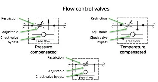
| Pressure-Compensated Flow Control | The variable flow symbol enclosed in a square box, with an internal arrow/spool mechanism. | The flow setting remains constant despite system pressure changes. The standard for reliable hydraulic speed control. |
Hydraulic Flow Control Symbol Deep Dive

A specific symbol often seen in fluid power is the combination of the basic restriction symbol with a compensator.
Symbol Breakdown: The symbol includes the adjustable orifice (diagonal arrow) and a secondary compensating spool (often shown as a spring-loaded pilot line) that automatically shifts to maintain a constant pressure drop across the adjustable orifice.
Purpose: This symbol immediately tells the engineer that the component will maintain a constant flow rate (Q) even if the pump pressure or actuator load changes dramatically.
Conclusion: Selecting the Right Valve
The term “flow control valve” is broad, encompassing simple balancing devices and complex pressure-compensated hydraulic units.
| If your primary need is… | Choose… | Rationale |
| Hydraulic Actuator Speed Control | Pressure-Compensated Flow Control Valve | Ensures constant speed regardless of load changes. |
| System Balancing (Water/HVAC) | Balancing Valve or Flow Limiter | Maintains design flow rates across multiple parallel paths. |
| Simple Throttling/Metering | Needle Valve | Offers high resolution for fine, manually adjusted flows. |
Mastering the distinct applications and reading the universal language of schematic symbols are key skills for professionals working with fluid dynamics and automation.