In the world of industrial automation, three terms appear almost every day: control valves, regulating valves, and instrument valves. All three are called “valves,” all can open or block the flow of fluid, yet they play completely different roles in real engineering systems.
In short:
Control Valve → The actuator that executes control commands
Regulating Valve → The throttling core that shapes the flow characteristics
Instrument Valve → The “invisible infrastructure” that ensures accurate measurement
To understand how they differ, we must look at how each one fits into a real control loop and how industries use them under different priorities.
1. A Simple Control Loop: Where Each Valve Really Belongs
Imagine a common task: maintaining stable pressure on a steam pipeline feeding downstream equipment.

A standard closed control loop includes three key parts:
Measurement
Pressure transmitter
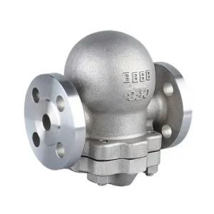
Instrument valves (manifold, needle valve, mini ball valve, etc.)
Control
DCS/PLC issuing commands
Execution
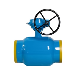
Control valve
Inside the control valve, the regulating valve body is the throttling element
These three components form a logical chain:
Instrument valves → determine whether the numbers you “see” are accurate
Regulating valve → determines whether each small change in signal results in predictable flow changes
Control valve → determines whether the system can execute commands smoothly and reliably
Understand this loop, and you understand their true engineering positions.
2. How Different Industries View These Three Valves
The same three types of valves play entirely different roles depending on the industry:
Chemical & Fine Chemical
The focus is on control quality:
Overshoot
Settling time
Valve linearity
Deadband
Poor regulating valve characteristics can cause reactors to swing between overheating and overcooling.
Power Plants (especially supercritical/ultra-supercritical units)
What matters most is safety and reliability:
High-temperature, high-pressure steam
Anti-erosion, anti-cavitation
Long-term, jam-free operation
Here, control valves are essentially life-protection devices.
Natural Gas Transmission & City Gas
Emphasis is on:
Pressure regulation stability
Tight shutoff
A single pressure-regulating valve is responsible for city-level safety.
Water Treatment & Environmental Protection
Priorities shift toward:
Cost-effectiveness
Easy maintenance
Mediums are mild, but the valve quantity is high; lifecycle cost matters more than extreme performance.
Different industries amplify different “character traits” of the three valves.
3. Control Valves: The Dynamic Actuator of the Process
In an automation system, a control valve is not merely a valve. It is the final control element—a dynamic response device.
Its purpose is not simply to open or close; it responds to the controller’s commands and converts them into measurable physical changes.
Signal Flow in a Control Valve
Controller output: 4–20 mA, pulse, or Fieldbus signals
Positioner: translates the signal into valve stem displacement
Actuator: pneumatic, electric, or electro-hydraulic; generates force or torque
Regulating valve body: performs the actual throttling
Thus, a control valve consists of:
Valve body (throttling)
Actuator (movement)
Positioner (signal correction & control)
It must solve three engineering challenges:
Process parameters continuously change → require real-time adjustment
Mechanical nonlinearity → needs linearization and compensation
Disturbances (pressure fluctuations, viscosity changes) → require stable response

A control valve is not a piece of hardware—it is a behavioral system.
Its quality is defined by whether it can execute commands reliably, not by material alone.
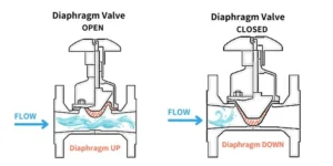
4. Regulating Valves: The Throttling Core of Process Control
A regulating valve is often mistaken for a control valve, but it is more like the engine cylinder—its sole mission is throttling.
Throttling is the physical essence of all flow regulation:
change resistance → change flow → change process variables.
What a Regulating Valve Must Deliver
Predictable flow characteristics (e.g., equal percentage)
Stability under high differential pressure
Resistance to cavitation, flashing, and erosion
Different structures—single-seat, double-seat, cage-guided, eccentric rotary, V-ball—exist to handle different energy dissipation mechanisms.
Pressure Drop Handling
Single-step drop → prone to cavitation and noise
Multi-stage/multi-hole/cage/maze → reduces energy density and eliminates cavitation
Flow Characteristics
Linear – flow proportional to opening
Equal percentage – gentle at first, sensitive later; great for large ΔP systems
Quick opening – suitable for on/off behavior
The regulating valve determines whether the process is controllable.
The control valve determines whether the system can execute the control.
One is physics; the other is system engineering.
5. Instrument Valves: The Hidden Infrastructure Behind Accurate Measurement
Instrument valves are often underestimated. They are not flashy and have no dynamic movement, but they determine the accuracy of every measurement.
Pressure transmitters, differential pressure transmitters, level instruments—all rely on proper:
isolation
venting/draining
impulse line integrity
The True Value of Instrument Valves: Avoiding Interference
They provide four hidden yet critical functions:
Isolation – protects sensors from sudden pressure shocks
Stabilization – dampens pulsations via impulse tubing
Venting/draining – prevents air locks and liquid traps
Calibration & switching – allows maintenance without process shutdown
A simple 3-valve or 5-valve manifold handles:
Process isolation
Venting/draining
Calibration and transmitter replacement
If instrument valves are selected or installed incorrectly, the entire system becomes blind—no matter how good the control or regulating valves are.
6. Selection Perspectives
Control Valve Selection
Focus on:
Is the application modulating, shutoff, or emergency isolation?
Required response speed & closing pressure
Reliability, fail-open/fail-close position
Signal modes (NO/NC, fail-safe position)
Regulating Valve Selection
Focus on:
Medium properties (corrosive? crystallizing? solids?)
Pressure drop and potential cavitation
Required flow characteristic (linear vs equal percentage)
Instrument Valve Selection
Focus on:
Pressure/temperature rating
Connection type (threaded, welded, compression fitting)
Required isolation level (double block and bleed?)
Space for maintenance
Sampling requirements
You are not selecting a “valve”—you are selecting a system behavior.
7. Typical Failures and Diagnostic Logic
Control Valve Issues
Slow response
Stiction
Hunting
Travel deviation
Causes often lie in positioner tuning, air supply, actuator friction, or spring preload.
Regulating Valve Issues
Noise
Cavitation
Trim erosion
Internal leakage
Stem sticking
These indicate early selection mismatches or improper throttling design.
Instrument Valve Issues
Micro-leakage
Blockage
Incomplete venting → measurement drift
Many “sensor faults” originate in the impulse line or manifold, not the transmitter.
A good diagnostic order is:
Measurement → Instrument valves → Regulating valve → Actuator → Controller
Most problems are not caused by PID.
8. Safety and Interlocks
Control Valves
Used in:
ESD systems
Combustion protection
Interlock shutdown
Critical requirements:
closes fast, closes tight, closes reliably.
Regulating Valves
In hazardous media:
Leakage class
Stem sealing (bellows seal, packing type)
These directly affect personnel and environmental safety.
Instrument Valves
A key part of isolation and bleed systems, ensuring the pressure is truly released before maintenance.
In a SIL (Safety Integrity Level) assessment, all three types form part of the SIF (Safety Instrumented Function) chain.
They are not separate components—they are one interconnected safety ecosystem.
9. Conclusion
To summarize in precise engineering language:
Control valve → governs dynamic response; it is the execution device
Regulating valve → governs energy dissipation and throttling; it is the process core
Instrument valve → governs signal quality; it is measurement infrastructure
Together they determine:
whether a system can be controlled
whether it can be controlled stably
whether it can be measured accurately
This is the fundamental logic of industrial control:
Measurement → Throttling → Execution.