In piping system installation, matching the valve’s flow direction with the medium’s path is critical for operational stability and safety. While some valves are bi-directional, many core functional valves have internal structures and sealing principles deeply integrated with flow dynamics. Incorrect installation can lead to sealing failure, erratic pressure, equipment damage, and even catastrophic accidents.
This article analyzes the valve types that require strict adherence to flow direction, explaining the core logic behind their design.
1. Globe Valves: The “Low-In, High-Out” Standard
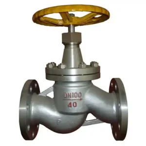
The globe valve is a primary example of a valve where flow direction is non-negotiable. Its design features a disc that moves perpendicular to the valve seat, creating a “tortuous” path for the fluid.
Why Flow Direction Matters:
Sealing Integrity: In standard configuration, fluid pressure acts under the disc, helping the stem’s mechanical force press the disc against the seat. If installed backward, the pressure acts on top of the disc, attempting to push it open, which can cause leakage even when the valve is tightly closed.
Erosion Protection: Proper flow allows the medium to pass smoothly under the disc. Reverse flow causes the high-velocity fluid to strike the sealing surfaces directly, leading to rapid wear and “wire-drawing.”
Operating Torque: Backward installation significantly increases the torque required to open or close the valve, potentially damaging the stem or the actuator.
2. Check Valves: The Single-Direction Guardians

Check valves (non-return valves) are designed specifically to prevent backflow. Therefore, flow direction is the most fundamental requirement for their operation.
The Mechanics of Failure:
Lift Check Valves: These rely on a spring or gravity. If installed backward, the fluid pressure will keep the disc firmly on the seat, effectively blocking the entire pipeline.
Swing Check Valves: Reverse installation prevents the disc from swinging open. Not only will the flow be blocked, but the back-pressure may deform the disc or hinge pin over time.
3. Pressure Reducing Valves (PRV): Safety and Stability

A PRV is a high-precision instrument that steps down high upstream pressure to a stable downstream pressure. Its internal feedback mechanism (diaphragm or piston) is built around a specific flow logic.
The Danger of Reverse Installation:
If installed backward, the high-pressure fluid directly impacts the feedback diaphragm and the adjustment spring. This prevents the valve from regulating. The result is usually an uncontrolled pressure surge where the downstream pressure equals the high upstream pressure, potentially causing pipe bursts or equipment explosions.
4. Safety Relief Valves: The Final Barrier

Safety valves are the last line of defense for pressure vessels. Their installation direction is a matter of life and safety.
The Logic of the Seal:
The system pressure must act under the valve disc to counteract the spring force. If installed backward, the system pressure acts on top of the disc, adding to the spring force. This makes it impossible for the valve to lift and relieve pressure, even if the system reaches dangerous, explosive levels.
5. Throttling and Needle Valves: Precision Control

Throttling valves use a tapered or needle-shaped disc to regulate flow. Like globe valves, they are designed for a specific entry point to maintain a stable flow coefficient ($C_v$).
Consequences of Error:
Turbulence and Noise: Reverse flow causes fluid to strike the non-working face of the needle, creating erratic flow patterns, vibration, and high-frequency noise.
Accuracy Loss: Precision control is lost when the fluid enters from the “wrong” side, as the pressure drop characteristics change entirely.
6. Steam Traps: Energy Efficiency and Drainage
Steam traps distinguish between condensate and steam based on density or temperature. This separation happens within a specific chamber configuration.
Operational Failure:
If installed backward, condensate cannot enter the trap effectively. This leads to “water hammer” in the steam lines, reduced heat transfer efficiency, and significant energy waste as live steam may leak through the system.
Summary: How to Avoid Installation Pitfalls
To ensure every valve is installed correctly, follow these three professional rules:
Trust the Arrow: Almost all valves with flow requirements have a permanent arrow cast or etched into the body. This is your primary guide.
Understand the Architecture: If the valve has an asymmetric internal design (like a PRV or a Globe Valve), it likely has a flow requirement. Symmetrical valves like Gate Valves and Standard Ball Valves are usually bi-directional.
The “Dry Cycle” Test: After installation, verify the operation. If a valve feels unusually difficult to turn or if the system pressure behaves erratically, immediately verify the flow direction against the manufacturer’s manual.
Correct flow orientation is not just a best practice—it is a baseline for industrial safety.