Abstract: Understanding Their Functional Conflict
While both the Gate Valve and the Check Valve are fundamental components in piping systems, they serve entirely different, and in some aspects, functionally opposite roles:
Gate Valve: An active, manual isolation device designed for starting or stopping flow (On/Off service). It provides minimal flow restriction when fully open.
Check Valve: A passive, automatic safety device designed to prevent reverse flow (backflow) and protect equipment.
Selecting the wrong valve can lead to operational failures, system damage (like water hammer), or costly maintenance.
Part I: The Gate Valve – Full Isolation and Minimal Restriction

The Gate Valve is named for its closing mechanism—a flat gate (or wedge) that slides perpendicularly into the flow stream to block the flow. It is one of the most common isolation valves in industrial use.
1. Structure and Working Principle
Core Component: A wedge-shaped gate or disc.
Operation: A multi-turn handwheel or actuator lifts and lowers the gate.
Fully Open: The gate is completely withdrawn from the flow path, creating a straight, unobstructed flow channel.
Fully Closed: The gate seats firmly against the valve body seats, blocking the flow.
Characteristics: Designed for full shut-off service.
2. Key Advantages and Limitations
| Advantages (Pros) | Limitations (Cons) |
| Low Flow Resistance: Minimal pressure drop when fully open. | Slow Operation: Requires multiple turns to fully open or close, unsuitable for quick shut-off. |
| Bi-directional Sealing: Can typically block flow from either direction. | Poor Throttling Control: Using it partially open causes severe vibration (chattering) and rapid erosion of the gate and seats. |
| Suitable for Slurries/Thick Fluids: The “gate” action can scrape solids away from the seat area. | Maintenance: Requires significant space for the bonnet and stem assembly when opening. |
3. Typical Application Positioning
Gate Valves are strictly used for isolation (on/off) purposes where the valve remains either completely open or completely closed. Common applications include:
Main pipeline shut-off points.
Isolation points for equipment maintenance.
Part II: The Check Valve – Unidirectional Control and Passive Safety

The Check Valve’s primary purpose is system protection. It is a self-activated valve that permits flow in one direction only and automatically closes to prevent reverse flow.
1. Structure and Working Principle
Core Mechanism: The valve disc or hinged flap is operated solely by the fluid’s pressure differential.
Operation:
Forward Flow: Fluid pressure overcomes gravity/spring force and pushes the disc open.
Reverse Flow: Back pressure immediately forces the disc back onto the seat, creating a seal.
Characteristics: Automatic, passive operation; requires no external power or human intervention.
2. Main Types and Their Considerations
| Type | Mechanism | Key Consideration |
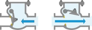
| Swing Check | Hinged flap swings open/closed. | Best for low-velocity flow; requires careful installation angle. |
| Lift Check | Disc lifts perpendicularly off the seat. | Ideal for high-pressure service; best installed horizontally. |
| Tilting Disc | Disc pivots away from the seat. | Excellent for minimizing water hammer due to its quick closing action. |
3. Typical Application Positioning
Check Valves are crucial safety components, almost always installed to prevent damage caused by backflow:
Downstream of pumps, compressors, and pressure-regulating devices.
Anywhere fluid must be prevented from flowing back into a lower-pressure area.
Part III: Head-to-Head Comparison – The Functional Conflict
Understanding this table is key to making the correct selection:
| Feature | Gate Valve | Check Valve |
| Primary Function | Isolation (Full On/Full Off) | Protection (Unidirectional Flow) |
| Control Method | Active (Manual or Actuated) | Passive (Fluid Pressure Differential) |
| Flow Restriction (Pressure Drop) | Very Low (when fully open) | Medium to High (Disc/hinge obstructs flow slightly) |
| Throttling Capability | Not Recommended (Leads to seat erosion) | Zero (Cannot be used for flow regulation) |
| Backflow Prevention | Yes (when manually closed) | Automatic & Instantaneous (Ideal for safety) |
| Installation Direction | Can usually be installed in any orientation. | Must be installed according to flow direction and specific model requirements (H/V). |
Part IV: The Selection Matrix – When to Choose Which Valve?
1. Choose a GATE VALVE When:
Your primary need is full, bubble-tight isolation for maintenance or emergency shut-off.
The valve will remain fully open or fully closed for long periods (minimal cycling).
Low pressure drop and minimal flow resistance are critical (e.g., in long-distance pipelines).
2. Choose a CHECK VALVE When:
Your primary concern is system safety and equipment protection from reverse flow (e.g., preventing pump cavitation or compressor damage).
The valve must operate automatically without any external power or intervention.
Protecting multiple sources/lines from cross-contamination is required.
3. The Co-existence Principle:
It is extremely common for both Gate Valves and Check Valves to be installed in sequence. For example, a Gate Valve might be installed on both sides of a Check Valve for service/maintenance isolation, while the Check Valve fulfills the safety role.
Conclusion
The Gate Valve and the Check Valve are not interchangeable. The Gate Valve is a manually operated stopper that ensures full isolation, while the Check Valve is an automatic protector that guarantees one-way flow.
By understanding their fundamental differences in structure, operation, and application, engineers can make the correct selection, ensuring system efficiency, longevity, and—most importantly—safety.