Why P&ID Symbols are the Engineer’s Universal Language
Piping and Instrumentation Diagrams (P&ID) are the core blueprint of any industrial process plant. Misinterpreting a symbol can lead to massive errors in design, operation, or maintenance. This guide provides a clear, authoritative breakdown of the most critical valve and equipment symbols, following widely accepted standards like ISA S5.1 and ISO 10628.
Note on Multi-Port Symbols: Unlike 2-way valves where the body symbol dictates the operational performance (e.g., Gate for isolation, Globe for regulation), 3-way and 4-way valve symbols prioritize Flow Path Configuration over internal structure. The core symbol focuses on how the stream is connected (L-port or T-port), which is the most critical piece of information for piping logic. The specific valve type (Ball, Plug, etc.) is usually detailed in the associated equipment list.
I. Core Valve Body Symbols: Flow Function Defined
The primary valve body symbol indicates the valve’s fundamental function (e.g., isolation, regulation, or multi-port switching).
1. Basic On/Off Isolation Valves (2-Way)
These symbols represent valves primarily used for starting and stopping flow (isolation).
A. Gate Valve Symbol
The Gate Valve symbol is typically represented by a stylized “M-shaped” or H-shaped symbol with an open center, signifying that when fully open, it provides a clear, unobstructed full port for flow isolation.

B. Ball Valve Symbol
The Ball Valve is often symbolized by a circle placed inside the process line. The circle represents the ball itself, indicating a quarter-turn, quick on/off isolation function often used in simple fluid service.

C. Globe Valve Symbol
The Globe Valve symbol uses a solid triangle or wedge shape inserted into the process line. This distinct feature represents the internal restriction and is used universally for any valve intended for flow regulation (throttling).

D. Butterfly Valve Symbol
The Butterfly Valve is symbolized by a circle intersected by a perpendicular line. This represents the disc within the flow path, indicating a lightweight valve used for isolation and some low-pressure regulation in large diameter lines.

E. Symbol Variations and Functional Substitutes
This section covers valves that often use the basic 2-Way isolation or throttling symbols but have unique functional or material considerations critical for selection.
E.1. Plug Valve Symbol

The specific P&ID symbol for a Plug Valve shows the internal plug (the cylinder) that rotates. This design is distinct from the Ball Valve’s simple circle and is used when the valve type must be visually unambiguous.
Symbol Structure: A line representing the flow path is interrupted by two short, parallel lines or a rectangle (representing the plug) where the line is broken, often with a 90° rotation indication.
E.2. Needle Valve Symbol

The Needle Valve is designed for highly precise, low-flow throttling. Its function is purely regulation, making it a specialized variation of the Globe Valve.
Symbol Used: It always utilizes the Globe Valve symbol (the solid triangle/wedge) to denote its function as a regulation/throttling device.
Unique Function: The long, tapered stem tip allows for extremely fine adjustment of flow rate, essential for instrument air lines or chemical injection.
E.3. Diaphragm Valve Symbol

The Diaphragm Valve isolates the fluid from the working parts (stem and bonnet) using a flexible diaphragm. Its symbol structure explicitly shows this unique internal feature.
Symbol Structure: The Diaphragm Valve symbol is distinct because it includes a semicircle or arched curve underneath the process line or within the valve body.
Meaning of the Curve (The Weir): This semicircle curve visually represents the Weir (a dam) and the flexible Diaphragm within the valve. This feature is key to distinguishing Diaphragm Valves, as it signifies:
Barrier Isolation: The fluid is completely sealed from the actuator.
Sanitary Design: The internal shape minimizes pockets where fluids can become trapped.
Unique Function: This symbol emphasizes the valve’s use in hygienic (sanitary), pharmaceutical, or highly corrosive applications.
E.4. Pinch Valve Symbol

The Pinch Valve uses a mechanical squeezing action to control flow through a flexible rubber sleeve.
Symbol Used: It often uses the Gate Valve symbol due to its isolation function, or sometimes a unique curved line symbol representing the squeezing action.
Unique Function: Exclusively used for slurries, powders, and abrasive media, as the internal sleeve is the only part in contact with the process fluid.
II. The Multi-Port Masters: 3-Way and 4-Way Valve Symbols (High-Traffic Focus)
Multi-port valves are essential for mixing and diverting flow streams. Their symbol must clearly show the number of ports and the internal flow path.
1. 3-Way Valve Symbols
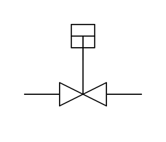
The 3-Way valve is represented by a square with three ports, defining either Diverting (Switching) or Mixing (Combining) flow paths.
A. L-Port (3-Way Diverting) Symbol
This symbol uses the circle body with internal lines representing an L-shaped path. It is used for switching flow from one source to one of two possible destinations.

B. T-Port (3-Way Mixing/Diverting) Symbol
This symbol uses internal lines representing a T-shaped path. It can be used for mixing two sources into one outlet, or for more complex diverting applications.

Engineering Insight (ISA Standard): Pay close attention to the arrows or lines within the circle, which denote the internal flow path in the valve’s standard or failure position.
2. 4-Way Valve Symbol
The 4-Way Valve is primarily represented by a square with four ports and two crossing internal paths. It is used for complex stream switching, most commonly for reversing the direction of a double-acting cylinder in actuator control systems.

III. Auxiliary Equipment Symbols
To provide a complete P&ID reference, we must include the symbols for the most common non-valve equipment.
A. Non-Return/Check Valve Symbol

This highly searched symbol is critical for safety and system integrity.
Symbol: Arrow (V-shape) placed in line
Description: Represents a valve that allows flow in only one direction. The symbol is typically a simple “V” shape within the process line, pointing toward the allowed flow direction.
B. Pump and Compressor Symbols
Pumps are the core component of any fluid system; their representation must be accurate.
1. Centrifugal Pump Symbol
The Centrifugal Pump is symbolized by a circle with a single triangle (or arrow) pointing outwards from the center.

2. Positive Displacement Pump Symbol
The Positive Displacement Pump (e.g., gear, piston) is symbolized by a circle with two smaller, filled triangles (or arrows) pointing outwards.

IV. Decomposed Symbols: Control and Actuation
A complete control valve assembly requires more than just the body symbol. This section breaks down the components that define how the valve operates.
1. Actuator Symbols
The actuator dictates the driving mechanism for the valve. The actuator symbol is usually drawn attached to the valve body.
A. Manual Actuator Symbol
Represented by a simple handwheel or lever shape. Used for infrequent, non-automated operation.

B. Pneumatic Actuator Symbol
Represented by a circle with a single line or arrow through it. This indicates the valve is driven by compressed air and is the most common symbol in automated control loops.

C. Electric (Motorized) Actuator Symbol
Represented by the letter “M” or “E” inside a circle or box. Used for slower, precise, or remote operations.

2. Control Signal and Instrumentation
These symbols show how the valve is connected to the central control system.
A. Valve Positioner (P/I or I/P)
Indicated by a square or circle attached to the actuator and the valve body, containing letters like P/I (Pneumatic to Current) or I/P (Current to Pneumatic). This indicates a device that ensures the valve stroke precisely matches the input signal.
B. Signal Lines
The type of line used to connect the valve/actuator to the control panel (DCS) indicates the signal medium:
Dashed lines: Typically represent pneumatic signals (compressed air).
Solid lines: Typically represent process or mechanical connections.
Unique lines (e.g., lines with slashes): Often used for electric or data link signals.
V. Authority and Standard Compliance
Authoritative Note: All symbols used in this guide adhere to the internationally recognized guidelines established by the Instrumentation, Systems, and Automation Society (ISA) S5.1 Standard for P&ID symbols. Always consult your project’s specific Legend Sheet as deviations may occur based on company or regional standards (e.g., ISO).