In municipal water works, a precise TS&V (Tapping Sleeve and Valve) installation detail is the difference between a long-term infrastructure asset and a high-cost emergency repair. Improperly installed tapping connections often lead to soil erosion, foundation settling, or catastrophic pipe bursts years later.
This technical guide dives into the engineering specifics of MJ (Mechanical Joint) Tapping Sleeves and provides a standardized reference for site engineers and project managers.
1. Deconstructing the TS&V Detail

A standard TS&V connection consists of three critical components, each with strict requirements on an engineering drawing:
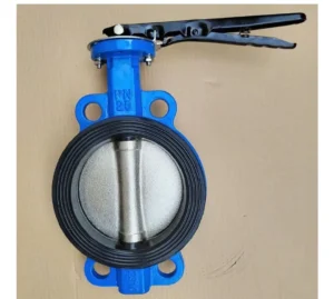
The Tapping Sleeve: This must provide full circumferential support to the existing pipe. For Water Main applications, sleeves are typically specified as Ductile Iron or Stainless Steel to handle high pressure and corrosive soil conditions.
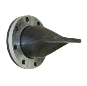
The Tapping Valve: The flange connection must feature a standardized Alignment Lip. This ensures the valve is perfectly concentric with the sleeve, preventing the cutting tool from striking the valve body during operation.
Gaskets and Sealing: High-performance EPDM 360-degree gaskets are mandatory to ensure a watertight seal against the rough exterior of old cast iron or AC pipes during the “wet tap” process.
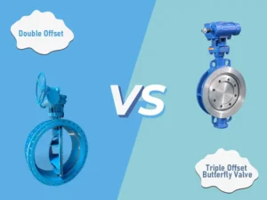
2. Mechanical Joint (MJ) vs. Flanged Connections
When searching for an MJ tapping sleeve, engineers are often weighing the pros and cons of different connection types:
MJ (Mechanical Joint): Offers superior flexibility. It allows for slight pipe deflection and is ideal for buried applications where ground movement or thermal expansion may occur. This is the gold standard for underground Water Mains.
Flanged Connection: Provides a rigid, high-strength joint. It is typically reserved for above-ground piping, pump stations, or vaulted environments where the valve assembly is easily accessible.
Expert Advice: For most buried infrastructure projects, we recommend the MJ Tapping Sleeve to mitigate long-term stress on the pipe wall.
3. The Valve Insertion Workflow
If your goal is not to add a branch but to add an isolation point, the search term valve insertion applies. Unlike traditional “cut-in” methods, the water main valve insertion process follows these steps:
Preparation: Clean the pipe exterior and precisely measure the Outer Diameter (OD).
Housing Installation: Bolt the two-piece Insertion Valve body around the pressurized pipe.
Pressure Milling: A temporary gate valve is used to allow a milling tool to cut a precise slot into the top of the live pipe.
Cartridge Deployment: The permanent valve cartridge is inserted through the housing, creating a new shut-off point without a single second of service interruption.
4. Engineering Checklist for Tapping Connections
To ensure the long-term reliability of a tapping connection, contractors must adhere to the following parameters:
Bolt Torque: Always use a calibrated torque wrench. Bolts must be tightened in a star pattern to the manufacturer’s specification (typically 75–90 ft-lbs depending on size).
Pressure Testing: Before the “coupon” is cut, perform a hydrostatic pressure test through the sleeve’s test plug at 1.5x the working pressure for at least 15 minutes.
Structural Support: Due to the weight of the tapping sleeve and valve, a Concrete Thrust Block or specialized pipe stand must be placed beneath the assembly to prevent shearing stress on the main pipe.
Conclusion
Mastering the TS&V detail is foundational for stable municipal water delivery. Whether you are specifying a Mueller-compatible tapping valve or sourcing high-pressure MJ tapping sleeves, professional technical support ensures your project is completed safely and efficiently.