In process control, a valve is much more than a simple gate; it is a dynamic orifice. The “character” of that orifice—how the flow rate responds to the movement of the valve stem—is what we call Flow Characteristics.
Choosing the right flow characteristics (480) is the difference between a stable, automated system and one that suffers from constant pressure surges or “hunting.” In this guide, we analyze the three fundamental valve curves (50) and how to select them based on your system’s requirements.
1. Defining Inherent vs. Installed Characteristics
Before looking at the curves, it is vital to distinguish between two states:
Inherent Characteristic: The curve produced in a laboratory where the pressure drop ($\Delta P$) across the valve is kept constant. This is what you find in a control valve size chart (30).
Installed Characteristic: The actual performance of the valve in the field, where pipe friction and pump curves cause the $\Delta P$ to vary as the valve opens.
2. The Three Fundamental Valve Curves
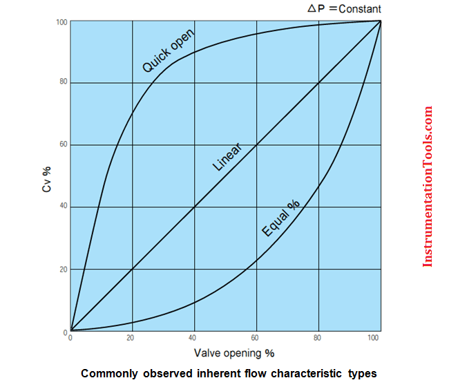
A. Quick Opening Valve
A quick opening valve (90) is designed to reach maximum flow capacity as quickly as possible. Usually, 90% of the total flow is achieved within the first 25% to 30% of the valve’s travel.
The Curve: A steep rise that flattens out quickly.
Best Use Case: On/Off service, emergency safety shut-off, or boiler blow off valves (140) where you need to purge the system instantly.
Common Design: Often seen in quick opening gate valves (30) or disk-style globe valves.
B. Linear Characteristic
In a linear control valve (40), the flow rate is directly proportional to the valve travel. If the travel is at 50%, the flow is at 50% of $C_v$.
The Curve: A straight diagonal line.
The Equation:

Best Use Case: Liquid level control and systems where the pressure drop across the valve remains constant regardless of the flow rate.

C. Equal Percentage Valve
The equal percentage valve (140) is the most versatile choice for process control. For equal increments of valve travel, the flow changes by an equal percentage of the flow that occurred just before the change.
The Curve: An exponential rise. At low openings, the flow is very precise; at high openings, the flow increases rapidly.
The Equation (30):

Best Use Case: Pressure control and temperature control loops where the pressure drop across the valve fluctuates significantly.

3. Comparison Table: Flow Characteristics at a Glance
| Characteristic | Flow Change per Unit Travel | Typical Application | Rangeability (20) |
| Quick Opening | Decreases as valve opens | Safety / Blow-off | Low |
| Linear | Constant | Level Control | Medium |
| Equal Percentage | Increases as valve opens | Pressure / Temp Control | High (30:1 to 50:1) |
4. Why “Rangeability” Matters
When reviewing a globe valve CV table (20), pay close attention to Rangeability. This is the ratio between the maximum flow and the minimum controllable flow. Equal percentage valves typically offer the highest rangeability, allowing them to control the process accurately even when the system is running at a fraction of its total capacity.
5. Selection Guide: Matching the Valve to the Process
How do you decide which is a quick opening valve (30) or an equal percentage valve for your project? Use these engineering rules of thumb:
Use Quick Opening for safety systems and “bypass” lines where you need a sudden burst of volume.
Use Linear if more than 40% of the total system pressure drop is concentrated at the valve.
Use Equal Percentage if the valve accounts for less than 40% of the system pressure drop (common in long pipelines with significant friction).
6. Sizing Tools: CV Charts and Tables
To ensure your control valves design (10) is accurate, you must calculate the Cv (flow coefficient). A control valve CV chart or a hydraulic valve size chart (20) will help you determine the physical size of the valve required to move your specific volume of fluid.