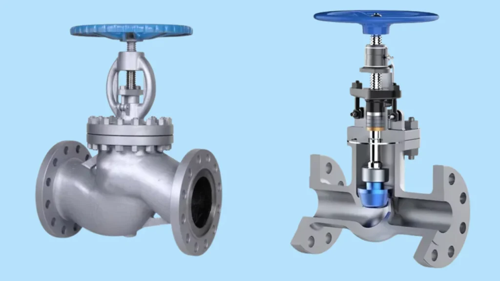
A globe valve is a linear motion valve with a movable disc (plug) and a stationary ring seat that controls flow by varying the size of the opening through which fluid passes. Unlike gate valves that simply open or close, globe valves excel at throttling—precisely regulating flow rate by adjusting how far the disc lifts off the seat. The name “globe” comes from the traditional spherical body shape, though modern globe valves use various body designs.
Globe valves are the go-to choice when you need to control flow rate, not just turn it on or off. Whether you’re regulating steam flow in a power plant, controlling cooling water in HVAC systems, or adjusting fuel flow in industrial burners, globe valves provide the precise, reliable control that gate valves and ball valves cannot match.
In this comprehensive guide, we’ll explain what makes globe valves unique, how they differ from gate valves, and when you should choose a globe valve for your application.
What Does a Globe Valve Look Like?
Before diving into technical details, let’s identify what you’re looking for:
External Appearance
GLOBE VALVE - EXTERNAL VIEW

         ┌────────────┐
         │ Handwheel  │ ← Turn to adjust
         └─────┬──────┘
               │
         ┌─────┴──────┐
         │   Bonnet   │ ← Top housing
         │            │
         ┌────────────┐
        ╱│            │╲
       ╱ │   Body     │ ╲ ← Globe-shaped
      ╱  │            │  ╲   (traditional)
     ╱   └────┬───────┘   ╲
    ╱         │            ╲
   ═══════════╪═════════════
         Inlet  Outlet
         (larger body than gate valve)
Key visual features:
- Bulbous body: Larger, more spherical than gate valve
- Handwheel on top: Centered directly over flow path
- Flow enters and exits at different levels: Not straight-through like gate valve
- Body is taller: Vertical height greater than gate valve
Size Comparison to Gate Valve
| Feature | Gate Valve | Globe Valve |
|---|---|---|
| Body shape | Slim, inline | Bulbous, offset |
| Height | Moderate | Taller (need more overhead) |
| Face-to-face length | Shorter | Longer |
| Flow path | Straight through | Changes direction |
Globe Valve Definition and Purpose
What Is a Globe Valve?
Globe valve definition: A valve that regulates flow in a pipeline by moving a disc perpendicularly to the direction of flow, creating a variable-size orifice that controls flow rate.
Globe Valve Purpose
The purpose of a globe valve is flow regulation—not just on/off control. Specific functions include:
| Function | How Globe Valve Achieves It |
|---|---|
| Throttling | Disc position varies orifice size, precisely controlling flow |
| Flow regulation | Linear relationship between disc position and flow rate |
| Frequent operation | Designed for repeated adjustments |
| Tight shutoff | Disc seats directly onto seat ring for leak-tight seal |
| Pressure reduction | Flow direction change and restriction reduces downstream pressure |
How Does a Globe Valve Work?
Understanding how globe valves work reveals why they’re ideal for flow control.
Globe Valve Operation
GLOBE VALVE INTERNAL OPERATION

CLOSED POSITION                 OPEN POSITION

    Handwheel                      Handwheel
       │                              │
    ┌──┴──┐                        ┌──┴──┐
    │Stem │                        │Stem │↑ Raised
    │  │  │                        │  │  │
    ├──┼──┤                        ├──┼──┤
    │  ▼  │                        │     │
    │ Disc│                        │ Disc│← Lifted
    │  ●  │← Seated                │  ●  │   off seat
    ├─────┤                        ├─────┤
   ╱│  █  │╲                      ╱│     │╲
  ╱ │  █  │ ╲                    ╱ │  ▲  │ ╲
 ╱  │  █  │  ╲                  ╱  │  ║  │  ╲
╱   │  █  │   ╲                ╱   │  ║  │   ╲
════╪═════╪════              ════╪══║══╪════
    →  ✗  →                      →  ║  →
    No Flow                      Flow passes
                                 through opening


THROTTLING POSITION (50% Open)

    Handwheel
       │
    ┌──┴──┐
    │Stem │← Partially raised
    │  │  │
    ├──┼──┤
    │  │  │
    │ Disc│← Partially lifted
    │  ●  │
    ├─────┤
   ╱│ ▲█▲ │╲ ← Restricted opening
  ╱ │ ║█║ │ ╲
 ╱  │ ║█║ │  ╲
╱   │ ║█║ │   ╲
════╪═║█║═╪════
    → ║ →
    Reduced flow
Step-by-Step Operation
Opening the valve:
- Turn handwheel counterclockwise
- Stem threads cause disc to rise
- Gap opens between disc and seat
- Fluid flows through the opening
- Flow increases as disc rises further
- Maximum flow at fully open position
Closing the valve:
- Turn handwheel clockwise
- Stem lowers disc toward seat
- Flow path becomes more restricted
- Flow decreases proportionally
- Disc contacts seat, stopping flow completely
- Leak-tight seal achieved
Throttling (flow control):
- Position disc partially open
- Opening size determines flow rate
- Linear relationship: 50% open ≈ 50% flow
- Can be set to any position for precise control
- Holds position for extended periods
Key Components and Function
| Component | Function |
|---|---|
| Body | Main pressure-containing vessel, houses all components |
| Bonnet | Top cover, provides access to internal parts |
| Disc (Plug) | Movable element that controls flow opening |
| Seat | Stationary sealing surface disc contacts when closed |
| Stem | Connects handwheel to disc, transmits motion |
| Packing | Seals around stem to prevent leakage |
| Handwheel | Manual operator for opening/closing |
Globe Valve vs Gate Valve: The Critical Differences
The most common question: globe valve vs gate valve—when do you use each?
Flow Path Comparison
GATE VALVE - STRAIGHT THROUGH        GLOBE VALVE - CHANGES DIRECTION

    ═════════════════════                  ═══════════╗
         Gate up                                ╔═════╝
    ─────────────────────                  ────║─────
    Flow straight through                      ║ Disc
                                               ║  ●
                                          ═════╩═════
                                          Flow changes
                                          direction
Comprehensive Comparison Table
| Feature | Globe Valve | Gate Valve |
|---|---|---|
| Primary function | Flow regulation/throttling | On/off isolation |
| Flow path | Changes direction (S-curve or Z-path) | Straight through |
| Pressure drop | High (due to direction changes) | Very low when open |
| Throttling ability | Excellent—designed for it | Poor—causes damage |
| Shutoff | Tight seal, leak-tight | Good seal |
| Operation speed | Slow (many turns) | Slow (many turns) |
| Disc/gate movement | Perpendicular to flow | Parallel to flow |
| Stem movement | Rising or non-rising | Rising or non-rising |
| Body size | Large, bulbous | Slim, compact |
| Pressure drop when open | Moderate to high | Very low |
| Cost | Higher | Lower |
| Maintenance | More complex | Simpler |
| Service life (throttling) | Long | Short (rapid wear) |
| Best for | Flow control, frequent adjustment | Isolation, infrequent operation |
When to Use Globe Valve vs Gate Valve
Choose GLOBE valve when you need:
- Flow rate control (throttling)
- Frequent adjustments
- Tight shutoff
- Pressure reduction
- Applications: cooling water control, steam regulation, fuel flow control
Choose GATE valve when you need:
- Full flow with minimal pressure drop
- On/off isolation only
- Infrequent operation
- Lower cost
- Applications: main shutoff valves, isolation valves
The Throttling Issue
Why gate valves fail at throttling:
Gate valve partially open:
- High-velocity flow cuts across gate edge
- Erosion damages gate and seat
- Vibration and noise
- Rapid wear and failure

Globe valve throttling:
- Disc designed for flow control
- Smooth flow across contoured disc
- Minimal wear even with constant adjustment
- Designed for this application
Types of Globe Valves
Different applications require different types of globe valves. Understanding the variations helps in proper selection.
By Body Design
1. Z-Body Globe Valve (Standard)

Design:
- Most common type
- Flow path resembles letter “Z”
- Inlet and outlet in straight line, at different levels
    ════════╗
            ║  ← Flow enters horizontally
         ╔══╝
    ─────║───── ← Disc/seat area
         ║
    ═════╩═════
            ↓ Flow exits horizontally
Characteristics:
- Simplest design
- Easy to manufacture
- Two direction changes (causes pressure drop)
- Most economical
Applications:
- General service
- Water, air, steam
- Non-critical applications
2. Y-Body Globe Valve
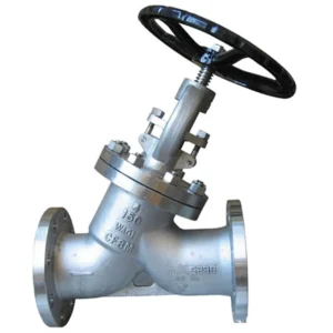
Design:
- Body and seat at 45° angle
- Flow path more streamlined
- Lower pressure drop than Z-body
         ╱
    ════╝
       ╱  ← Seat at 45°
      ╱
     ╱
    ╬════
    ↓
    Flow more streamlined
Characteristics:
- 30-40% less pressure drop than Z-body
- Higher flow capacity
- Suitable for horizontal or vertical installation
- More expensive than Z-body
Applications:
- High-pressure service
- Steam systems
- Where pressure drop is critical
3. Angle Globe Valve

Design:
- Inlet and outlet at 90° to each other
- One direction change instead of two
- Compact design
    ═══════╗
           ║
           ║ ← Single 90° turn
           ║
           ╬═════
           ↓
Characteristics:
- Lowest pressure drop of globe valve types
- Combines features of globe and angle valve
- Natural drainage when mounted at low points
- Self-cleaning effect
Applications:
- Condensate service
- Drain services
- Systems requiring 90° piping turn
- Erosive or dirty service
By Disc Design
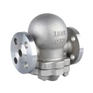
1. Conventional (Ball) Disc
Design: Simple spherical plug
Characteristics:
- General purpose
- Good shutoff
- Moderate flow control
2. Composition Disc
Design: Metal disc with soft seal insert (rubber, PTFE)
Characteristics:
- Bubble-tight shutoff
- Better for lower pressures
- Seal insert replaceable
3. Plug Disc

Design: Long, tapered plug
Characteristics:
- Best flow control
- Most linear flow characteristic
- Tight shutoff
4. Needle Valve

Design: Very long, tapered needle-point disc
Characteristics:
- Extremely precise flow control
- Small orifice sizes
- Excellent for low-flow regulation
Applications:
- Instrumentation
- Sample connections
- Gas chromatography
- Precise metering
By Stem Design
Rising Stem Globe Valve
Characteristics:
- Stem rises as valve opens (visible position indicator)
- Stem threads in bonnet
- Disc attached to stem
Advantages:
- Easy to see valve position
- Less wear on stem threads
Applications:
- Most common configuration
- General service
Non-Rising Stem Globe Valve
Characteristics:
- Stem rotates but doesn’t rise
- Threads in disc, not bonnet
- More compact
Advantages:
- Less vertical space required
- Stem packing not subjected to wear
Applications:
- Limited overhead space
- Underground service
Globe Valve Symbol
Understanding the globe valve symbol helps you read piping diagrams.
Standard Globe Valve Symbols
GLOBE VALVE SYMBOLS (P&ID)

1. Basic Globe Valve:

    ─────◐─────

    Circle with half-filled represents
    disc partially blocking flow


2. With Manual Operator:

         │  ← Stem/operator
    ─────◐─────


3. ISO Standard Symbol:

    ─────☐─────
         ▲
    (Square with triangle pointing to flow)


4. Detailed Symbol:

    ───────┬───────
           │
        ┌──●──┐  ← Disc shown
        │     │
    ────┴─────┴────


5. Angle Globe Valve:

    ───────┐
           │
           ◐
           │
           └─────
Symbol Components
| Element | Meaning |
|---|---|
| Half-filled circle | Disc position adjustable |
| Vertical line above | Manual handwheel operator |
| Arrow | Flow direction |
| Letters (HCV, FCV) | Control function (Hand Control Valve, Flow Control Valve) |
Reading Globe Valve Symbols on Drawings
When you see a globe valve on a P&ID:
- Check flow direction arrow: Ensure proper installation orientation
- Note control designation: HCV (manual), ACV (automatic), etc.
- Verify size marking: Usually shown as “2” GV” = 2-inch globe valve
- Check actuation: Hand wheel, motor, pneumatic
Globe Valve Diagram and Components
Cross-Section Diagram
GLOBE VALVE - DETAILED CROSS SECTION

         ┌──────────┐
         │Handwheel │ ← Manual operator
         └────┬─────┘
              │
         ┌────┴─────┐
         │ Packing  │ ← Seals stem
         │  Gland   │
         ├──────────┤
         │  Bonnet  │ ← Removable cover
         ├──────────┤
        ╱│          │╲
       ╱ │  Stem    │ ╲
      ╱  │    │     │  ╲
     ╱   │  ┌─┴─┐   │   ╲
    ╱    │  │Disc│  │    ╲ ← Body
   ╱     │  └─┬─┘   │     ╲
  ╱      ├────●─────┤      ╲
 ╱       │  Seat    │       ╲
╱        │  Ring    │        ╲
═════════╪══════════╪═════════
    Inlet     │      Outlet
              ↓
         Flow direction
Parts of a Globe Valve
| Part | Material (Typical) | Function |
|---|---|---|
| Body | Cast iron, bronze, carbon steel, stainless | Pressure boundary |
| Bonnet | Same as body | Provides access, houses packing |
| Disc | Bronze, stainless, stellite | Controls flow |
| Seat ring | Bronze, stainless, hard-faced | Sealing surface |
| Stem | Stainless steel, monel | Transmits motion to disc |
| Packing | PTFE, graphite | Seals stem |
| Handwheel | Iron, aluminum | Manual operator |
Globe Valve Function and Applications
What Is a Globe Valve Used For?
The uses of globe valve span many industries because of their excellent control characteristics.
Industrial Applications
Steam Systems:
- Main steam flow control
- Condensate regulation
- Steam tracing control
- Boiler feedwater
HVAC Systems:
- Cooling water regulation
- Heating water control
- Balancing valves
- Coil isolation and control
Process Industries:
- Chemical feed control
- Flow measurement isolation
- Sampling points
- Pressure reduction
Power Generation:
- Turbine bypass
- Feedwater control
- Extraction steam
- Auxiliary systems
Oil and Gas:
- Wellhead control
- Gas metering stations
- Pressure regulation
- Flow control
Residential/Commercial
Building Services:
- Radiator control valves
- Domestic hot water temperature control
- Boiler makeup water
- Pressure reducing stations
Utilities:
- Water distribution control
- Pressure management
- Flow balancing
- Meter isolation
Globe Valve Function in Control Systems
Globe valves are ideal for automatic control because:
- Linear flow characteristic: Predictable relationship between position and flow
- Smooth operation: No sudden changes in flow
- Precise positioning: Can hold any position accurately
- Responsive: Quick response to control signals
- Repeatable: Returns to same flow at same position
Globe Valve Selection Criteria
When to Choose a Globe Valve
Select a globe valve when you need:
✅ Flow regulation/throttling
✅ Frequent operation
✅ Tight shutoff
✅ Automatic control capability
✅ Pressure reduction
✅ Applications requiring adjustment
Don’t choose globe valve when:
❌ Minimal pressure drop critical
❌ Only on/off operation needed
❌ Infrequent operation (isolation only)
❌ Cost is primary concern
❌ Space is very limited
Sizing Considerations
Flow coefficient (Cv):
- Measures valve flow capacity
- Higher Cv = greater flow capacity
- Must be sized for application flow and pressure drop
Pressure drop:
- Globe valves inherently create pressure drop
- Y-body 30-40% less than Z-body
- Angle globe 40-50% less than Z-body
- Size to balance control range vs pressure loss
Velocity limits:
- Steam: 200-300 ft/sec maximum
- Water: 10-15 ft/sec typical
- Erosive service: reduce velocities 50%
Globe Valve Installation and Maintenance
Installation Best Practices
Flow direction:
- Generally, flow enters under the seat (pressure assists closing)
- Check manufacturer marking—arrow shows correct flow direction
- Some designs allow either direction
Orientation:
- Stem vertical preferred (disc closes by gravity assist)
- Horizontal stem acceptable for most designs
- Check manufacturer specifications
Piping considerations:
- Support piping independently (don’t use valve as support)
- Allow clearance above valve for bonnet removal
- Consider access for maintenance
Maintenance Requirements
Periodic inspection:
- Check packing for leaks
- Verify smooth operation
- Listen for unusual noise (cavitation, erosion)
- Monitor pressure drop
Packing adjustment:
- Tighten packing gland if stem leaks
- Don’t overtighten (causes binding)
- Replace packing when adjustment no longer stops leaks
Seat maintenance:
- Lap seats if leaking (minor wear)
- Replace seat ring if severely damaged
- Check disc for erosion or damage
Service interval:
- High-cycle applications: Annual inspection
- Moderate use: Every 2-3 years
- Critical service: More frequent
Common Globe Valve Problems
| Problem | Symptoms | Causes | Solutions |
|---|---|---|---|
| Stem leaking | Fluid dripping from packing | Worn packing, loose gland | Tighten gland, replace packing |
| Hard to operate | Excessive force needed | Dried packing, corrosion, pressure differential | Lubricate, replace packing, check direction |
| Won’t close completely | Flow continues when closed | Damaged seat, debris | Clean, lap or replace seat |
| Excessive pressure drop | High loss across valve | Valve undersized, partially closed | Verify sizing, check position |
| Noise/vibration | Rattling, humming | Cavitation, high velocity | Resize, add trim, reduce differential |
| Erosion damage | Metal loss on disc/seat | High velocity, abrasive fluid | Hard-face trim, reduce velocity |
Globe Valve vs Other Valve Types
Globe Valve vs Check Valve
| Feature | Globe Valve | Check Valve |
|---|---|---|
| Operation | Manual control | Automatic (flow-activated) |
| Function | Flow regulation | Backflow prevention |
| User control | Full control of position | No control |
| Typical use | Control applications | Protection |
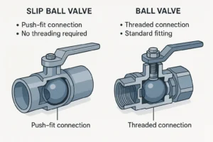
Globe Valve vs Ball Valve
| Feature | Globe Valve | Ball Valve |
|---|---|---|
| Operation | Multi-turn (slow) | Quarter-turn (fast) |
| Throttling | Excellent | Poor |
| Pressure drop | High | Low |
| Shutoff | Tight | Tight |
| Best for | Flow control | On/off service |
Frequently Asked Questions
Why is it called a “globe” valve?
Traditional designs had spherical (globe-shaped) bodies. Modern globe valves often have non-spherical bodies but retain the name.
Can I use a globe valve for on/off service?
Yes, but it’s more expensive than necessary. Gate or ball valves are more economical for simple on/off applications.
What’s the difference between globe and needle valves?
Needle valves are a type of globe valve with a long, tapered disc for extremely precise flow control—typically for small flows and instrumentation.
Do globe valves work in both flow directions?
Most are designed for flow “under the seat” (entering below disc), but some designs work in either direction. Check the flow arrow on the body.
How long do globe valves last?
With proper maintenance: 10-20+ years. High-cycle control applications may need seat refurbishment every 5-10 years.
Conclusion
Globe valves are essential flow control devices designed for throttling and regulation applications where precise control is needed. Unlike gate valves that simply open or close, globe valves provide excellent flow modulation through a perpendicular disc movement that creates a variable orifice.
Key takeaways:
- Globe valves excel at flow control and throttling—their primary purpose
- They create higher pressure drop than gate valves due to directional flow changes
- Available in Z-body, Y-body, and angle configurations for different applications
- Never use gate valves for throttling—always use globe valves when flow control is needed
- Y-body and angle designs reduce pressure drop by 30-50% vs standard Z-body
- Ideal for automatic control systems due to linear flow characteristics
Whether you’re controlling steam flow, regulating cooling water, or adjusting fuel delivery, globe valves provide the precise, reliable control that makes them indispensable in modern piping systems.
Need help selecting the right globe valve? Contact our technical team for application-specific recommendations and sizing assistance.